1. Background
Infinity Mirror is a watch face for the Xiaomi 17's rear screen. Since this is a fairly standard request and there's no big launch pressure, I wanted to try out a few ideas.
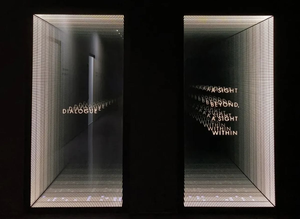
We drew inspiration from the "Infinity Mirror" shown above. It uses two one-way mirrors to bounce a light source back and forth, creating a deep, seemingly endless effect. From different angles it looks different, almost like staring into a real abyss.
The rear screen on the Xiaomi 17 is like a window cut into the phone's body. We can create a similar illusion using sensor data and real-time rendering techniques.
2. Design Idea
In 3D, you can do this with a simple camera setup. I've made a quick animation to show it. The lights don't move; as the viewing angle changes, you see different reflection layers inside the 'window'. Think of the rear screen as that window. In real use, the user's eyes stay put and they rotate the phone. We can read the phone's rotation and render the right frames to make it look like there are many lights behind the glass.
There are two key factors that characterize this rendering approach:
- Perspective: The first ring must match the phone's perspective in the physical world. It should appear painted onto the glass and track the device's rotation.
- Window size: The rear screen size is fixed. More tilt means a smaller visible window.
A top view helps to explain this. The screen edges and the eye define the top-view frustum. The angle at the eye is the field of view (FOV). As the phone rotates, this effective FOV changes, whereas standard rendering typically keeps the FOV fixed.
The animation illustrates a simplified single-axis (2D) rotation. In reality, there are three degrees of freedom, which increases the complexity.
3. Rendering
We want a projection that keeps the image plane fixed in world space, even when the eye moves. This problem is well studied in the game engines. The technique is known as Portal Projection.
3.1. Portal Projection
3.1.1. Define Image Plane
To define the plane, we use a point on the plane, a normal , and two unit tangent vectors and that lie on the plane. For simplicity, let the screen center be the origin, choose orthogonal axes aligned with the screen edges, and take the normal to point into the screen.

Then we have:
| Def | Expr |
|---|---|
3.1.2. Build Projection Matrix
We could use classic Model-View-Projection (MVP) composition to build an asymmetric (off-axis) frustum. Here I prefer a more direct approach. Lengyel, Oblique View Frustum
Take any point in world space, connect it to the eye . Find the intersection with the plane.
Here, is the projection of onto the image plane along the ray from to , which is exactly what we need. Implementation in the vertex shader is straightforward:
// Eye position in world space
uniform vec3 EyePos;
// Plane point and normal
uniform vec3 PlanePoint;
uniform vec3 PlaneNormal;

void main() {
  vec3 worldPos = (MODEL_MATRIX * vec4(VERTEX, 1.0)).xyz;
  vec3 rayDir = normalize(worldPos - EyePos);
  float denom = dot(PlaneNormal, rayDir);
  float t = dot(PlanePoint - EyePos, PlaneNormal) / denom;
  vec3 projected = EyePos + rayDir * t;
  // Map projected.x, projected.y to [-1,1] using your plane axes and size
  // ...
}
3.2. Comparison
In perspective projection, the rings 'self-rotate' instead of following the screen rotation.
4. Interaction
The materials and lightings are just standard PBR. Most of the effort went into sensor data processing to make the interaction feel natural, stable, and responsive.
4.1. Sensor Data Handling
This project is built upon Android platform. Android provides a variety of sensor data. (see: Android Motion Sensors.) The data categories we use are:
| Sensor | Purpose |
|---|---|
| Gyroscope | Angular velocity |
| Linear Accelerometer | Linear acceleration |
| Gravity | Gravity vector components |
| Magnetometer | Magnetic field components |
We estimate device pose by integrating angular velocity over time, with gravity- and magnetometer-based corrections to limit drift:
Where:
- current orientation
- previous orientation
- frame delta
- current angular velocity
- correction from other sensors to limit drift
From here, given an initial orientation , we can solve device orientation at any given time.
The formula looks heavy, but the idea is basic. Putting it down mathematically helps clarify my thinking.
4.1.1. Initial Orientation
On first launch, we use gravity vector and magnetometer readings to set the device's world-space orientation.
function orientate_by_mag_and_grav() {
  // Magnetometer
  const p_mag  = get_magnetometer()
  // Gravity
  const p_grav = get_gravity()

  let device_basis = new Basis()
  // Device y points opposite to gravity
  device_basis.y = -p_grav.normalized()
  // Device x = plane normal of (gravity, magnetic north)
  device_basis.x = device_basis.y.cross(p_mag)
  // Device z = third orthogonal axis
  device_basis.z = device_basis.x.cross(device_basis.y)
}
We adopt a left-handed coordinate system here where points east, points up, and points north. Specifically, with the world basis taken as the identity:
The device is held upright (screen vertical), with the camera facing north.
4.1.2. Discrete Integration
Sensor noise is a constant concern. Raw gyroscope data readings introduce jitter if applied directly to rendering, so the view may rotate slightly even when users hold their phone still. We mitigate this with a small deadband (quantization threshold), suppress angular changes below the threshold to remove tiny motions.
function deadband(gyro) {
  let r = new Vector3();
  r.x = round(gyro.x * 10.0) / 10.0;
  r.y = round(gyro.y * 10.0) / 10.0;
  r.z = round(gyro.z * 10.0) / 10.0;
  return r;
}

// GLOBAL
let BASIS_WORLD;

function on_init() {
  // ...
  BASIS_WORLD = orientate_by_mag_and_grav();
  // ...
}

function accumulate(p_gyro, dt) {
  // Keep 1 decimal. Remove micro jitter.
  const gyro = deadband(p_gyro);

  let r = Basis()
  // Discrete integration
  r = r.rotated(BASIS_WORLD.x, -gyro.x * dt)

  r = r.rotated(BASIS_WORLD.y, -gyro.y * dt)
  r = r.rotated(BASIS_WORLD.z, -gyro.z * dt)
  BASIS_WORLD = r * BASIS_WORLD
}
4.1.3. Easing
There are three motion-sensor related issues that require extra attention:
- Sensor updates are not at a fixed rate.
- Frame intervals are variable due to inconsistent processing times.
- User motion can produce regional spikes. (e.g. hand shake, walking, vehicle vibrations, etc.)
Because of processing limits, sensor sampling rates are bounded, so the data are discrete and often uneven. When a spike is captured, the rendered view can jump noticeably, causing flicker. A common solution is to ease between value updates (i.e. interpolation, smoothing) rather than applying raw changes.
Easing has two components: interpolation and curve.
- Spherical interpolation
There are two common mathematical representations for rotations: Euler Angle and quaternion. Their pros and cons are covered in many great resources, e.g. videos by Freya and 3Blue1Brown. Here I will highlight a special scenario that makes Quaternions necessary in our application.
Interpolation in euler angle does not follow the expected path
- Spring curve
We do not need a physically accurate spring simulation, a visual approximation is good enough in our case. Given a target , and the previous value , update the current value as:
This simple update produces a sufficiently spring-like behaviour. Let's sketch a brief derivation to see why.
Consider a damped spring system defined by:
Let , , :
In our update function, treat :
From and , the first derivative of our update and the physical model share the same form: velocity is proportional to the error. In other words, the farther the current value is from the target, the faster it moves toward it.
4.2. Over-limit Handling
Users may rotate beyond 360°, even making multiple turns. In a physical infinity-mirror setup, that would place you 'behind' the window (outside the visible half-space). To keep the experience stable, we add an over-limit policy.
- Relative Rotation
In Initial Pose section, we resolved orientation in absolute coordinates using gravity and magnetic north. As a result, if the user faces south, they end up 'behind' the mirror and nothing appears. Obviously, we can't require users to face north just to read the time.
We can use the initial pose as an anchor and define a relative coordinate frame to rotate within it.
// GLOBAL
let BASIS_WORLD: Basis;
let Q_ANCHOR: Quaternion;
let Q_WORLD: Quaternion;

function on_init() {
  // ...
  BASIS_WORLD = orientate_by_mag_and_grav();

  Q_WORLD = Quaternion.from(BASIS_WORLD);
  Q_ANCHOR = Q_WORLD;
  //...
}
- Spring-follow
If the angle exceeds a threshold, use a spring to move the anchor toward the user. In physical terms, it's like turning the mirror to face them.
function update_anchor() {
  // Relative spherical distance
  const angle = Q_ANCHOR.angle_to(Q_WORLD);
  if (angle > MAX_ANGLE) {
    // Move anchor
    Q_ANCHOR = Q_ANCHOR.slerp(Q_WORLD, ANCHOR_MOVE_FACTOR);
  }
}

function on_update(dt) {
  // ...
  update_anchor();
  // Relative rotation for render
  const q_diff = Q_ANCHOR.inverse() * Q_WORLD;
  // ...
}
By combining relative rotation with the spring-follow mechanism, the experience remains stable even under large motions.
4.3. AOD
AOD aims to save power and reduce burn-in risk. We do:
- Lower brightness: 30% of normal
- Simplify rendering: thinner font, hide inner rings behind the camera, fewer edge rings
5. Future Improvements
- More colors and materials
Right now there is only white theme. Richer environments and lighting will help. Rings can use more complex materials as well.
View some product shots I took here.